Background
If you havent already, checkout the previous Post which provides an introduction to the PcDuino8 Uno
I felt that the serial debug section needed its own explanation simply because it was nowhere near as straightforward as it should have been, and even with the daily experience i have using these devices i was stumped when trying to get the device to work. I even sent back my second PcDuino8 Uno citing that the Serial debug port was not functioning only for me to realize (thanks to a helpful thread on the forums) that i was plugging the connectors in the wrong way round! I cant be completely blamed for this and here is why..
At first I thought, oh crap my cable is broken, i should send it back to Amazon, I held off though until the arrival of my PcDuino3 Nano so that i could be sure that it was the cable and not the board.
The PcDuino3 Nano arrived and the cable functioned and spat beautiful U-Boot jargon into my terminal. I tried again on the PcDuino8 Uno and it was dead, No serial output at all, The board worked fine but i didn’t want to keep a board that didn’t have that low level access to serial debugging which i may need in the future to configure U-Boot. So I sent it back and ordered a new one, which came a week later.
Again this board also failed to output any serial information, I don’t have a multi meter so i couldn’t check if there was an actual current running through the headers. I burnt fresh images onto separate sd cards and still nothing worked, I was wondering how it could be possible for serial debugging to work on one board and not the other, I recalled it working on my first ever PcDuino8 Uno which i accidentally fried, so why wasn’t it working now?
I was close to sending this third board back, confused that two in a row had faulty serial debug modules..
All this time I had been double checking that i had inserted the headers in correctly, I was following the guide to the letter and the book “Getting Started with pcDuino3” confirmed that I was indeed inserting them correctly, and the most solid concrete fact i had was that this worked on my PcDuino3 Nano.
I stumbled across this forum thread where a community member had the same issue only for him to thankfully mention how he fixed it.
He swapped the RX and TX Terminals, It was an honest to god palm to forehead moment, where firstly i couldn’t believe i hadn’t tried it, and secondly, Why LinkSprite? Why the hell did you switch the RX and TX terminals on the PcDuino8 Uno compared to the PcDuino3 Nano?
I don’t have all the boards so i cant tell if they are all using random configurations but i suspect that the PcDuino8 Uno is the only one where it is reversed.
Hardware
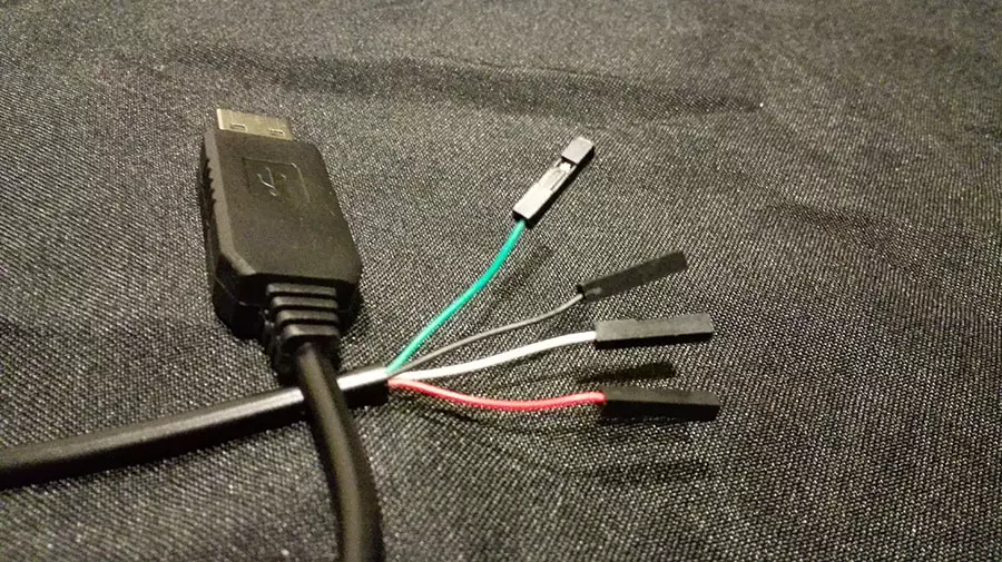
Serial Debug Cable (Armorview PL2303HX USB To TTL To UART)
I purchased this cable from Amazon, If you have issues getting the drivers from Prolific working you might want to try the following driver (This blog post explains it further), as it was all I managed to get functioning on Windows 10.
Also you may experience unexplained Blue Screens of death when you are using the cable with these drivers, I don’t know why but i guess Prolific had a point when they dropped support for the cable on windows 8+.
Be sure to save frequently and if you really don’t need to use the Serial Debug cable you can always SSH into the device and use that.
Setup
Initially you want to make sure that when the device is plugged into your PC even before you connect it to your board that its drivers do not return error code 10. Again this blog post explains what to do in that situation. If the device reports that it is working correctly enter its settings and set the baud-rate.
My Cable Wires are labeled as the following
- Black cable—–GND—–Grounded Wire
- Green cable—–TXD—–Transmitter
- White cable—–RXD—–Receiver
- Red cable ——+5V—–Extra Power (Don’t put this into your board, it will probably fry!)
Connect the device like the following image:
White (RX) – Black (GND) – Green (TX)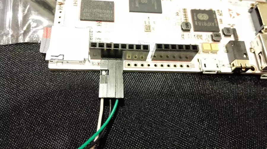
And not like this otherwise you will get no signal..
Green (TX) – Black (GND) – White (RX)
Unless you are using another board like PcDuino3 Nano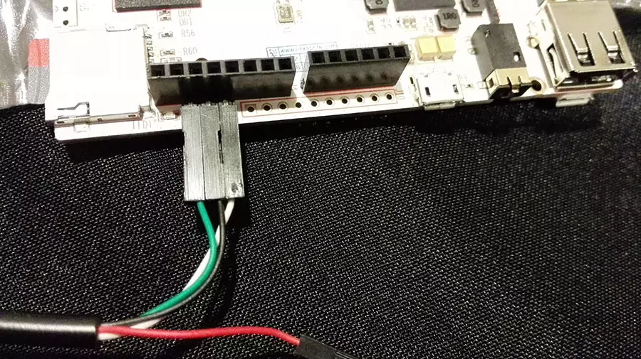
Testing
Now we can test if there is any serial communication on these headers. We will need some software to achieve this. My Personal preference is Putty. Alternatives include:
Lets get cracking.
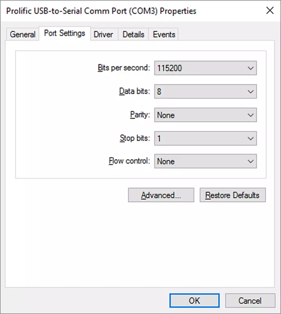
- Use your device manager to check which COM Port your serial cable is making use of. (In my case it is COM3)
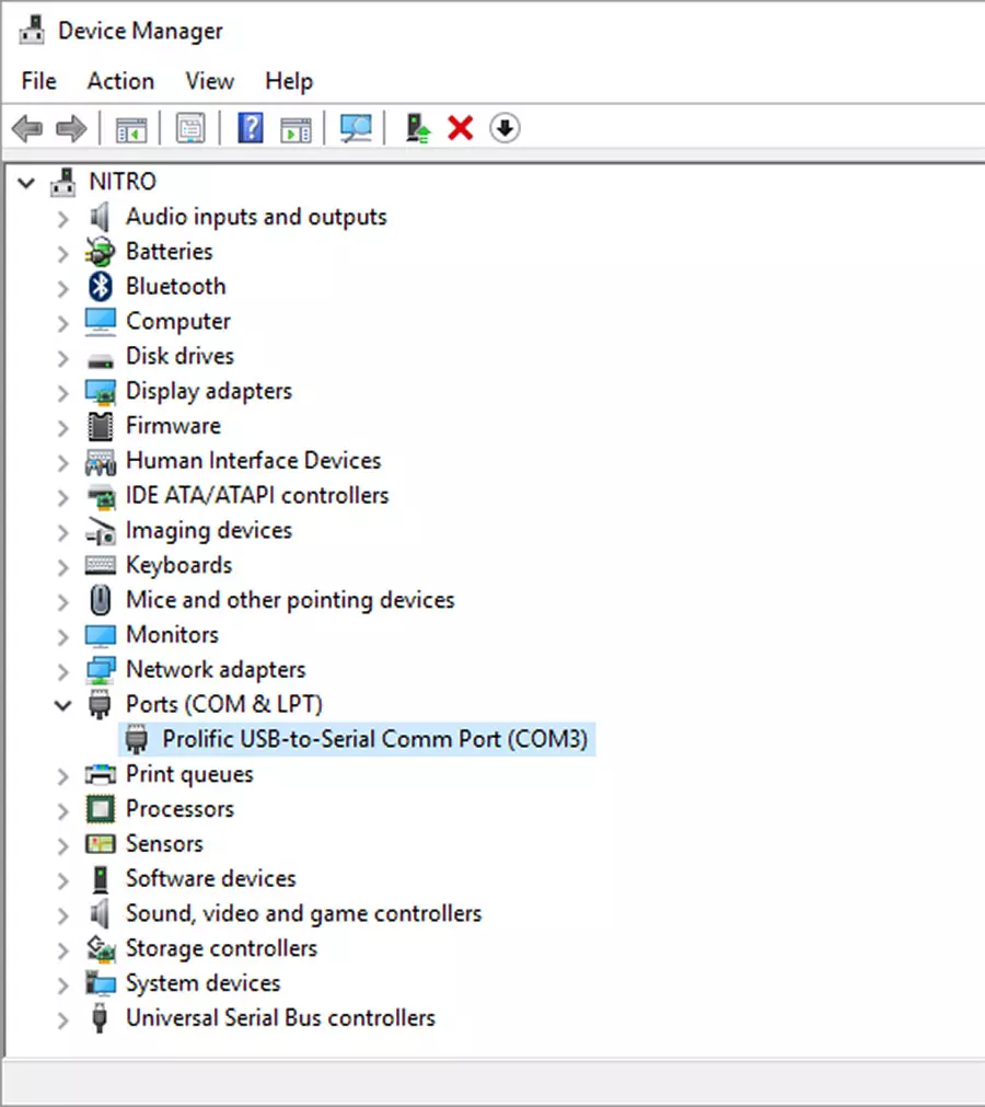
- Right click on the device and select Properties. Match the properties from the Image, the most important being the Baudrate which should be 115200
- In Putty enter the following to open a serial connection to whatever COM Port your device is on.
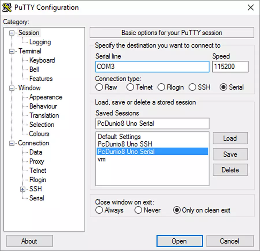
- Open the Connection
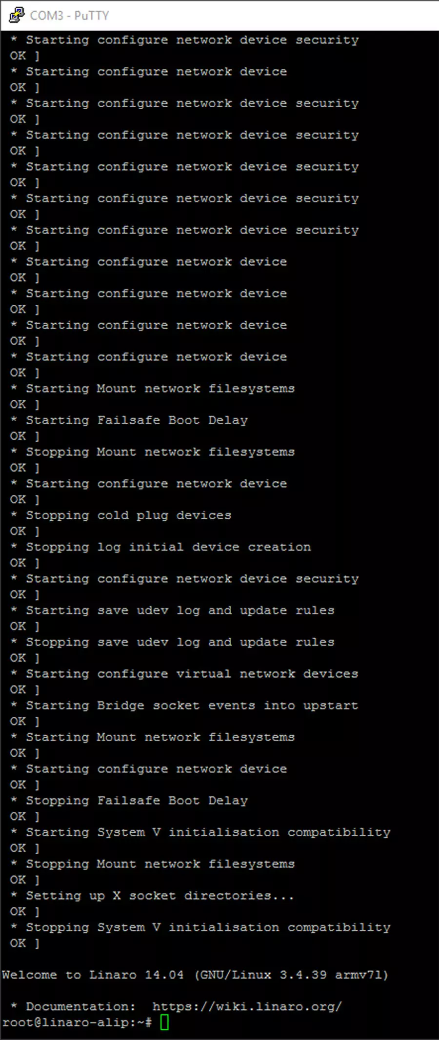
- If your device was already running hit return a few times to see Linaro respond with a prompt
- If you start your machine fresh you will see the terminal flooded with U-Boot information
- If not swap your RX and TX cables and try again.. I wouldn’t be surprised if the headers were different even from board to board of the same type.
And that’s it you now have low level serial debug access to your board which you can use to traverse the directories, edit files and your run of the mill terminal activities.
The next Post will cover networking by connecting the PcDuino directly to a PC and using SSH as an alternative to the Serial Port and VNC Viewer to look at the Linaro desktop as an alternative to using a physical monitor.
Have Fun Tinkering!
References
These are some places that may come in handy for you when getting started with this board.